Some of it's features include:
- Front Facing Sonar
- Drill Motor Drive
- Dinsmore/Vector Compass
- PVC & Wood Chassis
- Basic Stamp 2 Microcontroller
Conclusions with this bot were mixed. Although, I got results with the robot the amount of error with the algorithms I used made the design more difficult. I since rebuilt the robot Feynman2 to eliminate some of the following :
- 180° Sonar field of view.
- Arm kept hitting objects exposing it to damage.
- Bumpers not sufficient.
- No DIRS, Infrared Sensor
- Too Wide & Support flimsy
Here are some early pictures of Feynman 1.
 |
 |
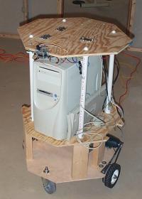 |
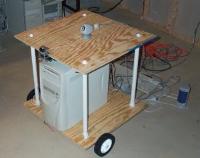
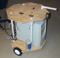
| 1st Design - Early August | 2nd Design - Late August | 3rd Design - Mid September |
 Click For Larger Image |
 |
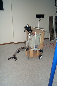
| 3rd Design w/Sensors - Mid October | 4th Design w/Sensors - Mid May |
The Chassis
I am on the 3rd design of Feynman’s Chassis. I do not think I am going to be happy until I get some nice gear motors, chain drive, and ALL Aluminum chassis, but for now I'll continue to work with what is CHEAP.
Design 1 - Plywood and PVC
| Pros | Cons |
| - Cheap - Easy to form |
- Precision Difficult - Not to sturdy - Difficult to modify and access components. - Too wide to get through doors. - Turning radius too large. - Did not look too good. - Too fast |
Design 2 - Plywood, PVC, Octagonal Shape, Centered Drive Placement and Access Door
| Pros | Cons |
| - Cheap - Easy to form - Better ability to get through doors. - Difficult to modify and access components. - Better turning radius - Looks Better |
- Precision Difficult - Not too sturdy - Too fast |
Design 3 - Plywood, PVC, Octagonal Shape, Centered Drive Placement, Access Door, Geared 4:1 Drive, and Steel shafted drive with bearings on hardwood base.
| Pros | Cons |
| - Cheap - Easy to form - Better ability to get through doors. - Difficult to modify and access components. - Better turning radius - Looks Better - Precision with hardwood better than plywood - Wood base make robot platform more sturdy - Speed about right. |
- Precision Difficult - need to replace rest of body now that prototype is validated. |
More Images of Design #3
fig 4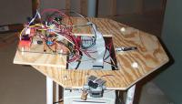 |
fig 5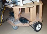 |
| Fig 4 - The Access Panel Here is the Basic Stamp 2, x2 Novak Rooster Motor Controllers, and lotsa wire. |
Fig 5 - The Drive System Here you can see the Black & Decker cordless drill motors, casters, and mounts. |
fig 6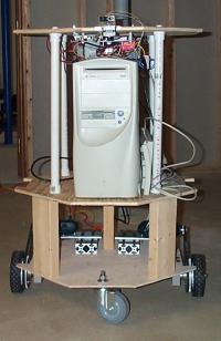 |
fig 7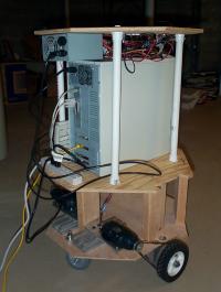 |
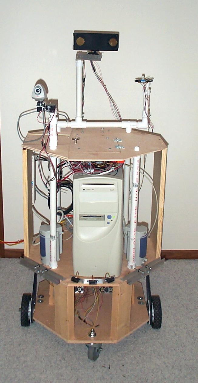
| Fig 6 - The Front View Here you can see the base. I have made it this height for when I plan to go FULL-MOBILE and I can place a car battery in there. You can see the PC on level 2, with the IR Range Finder on level 3in the center. |
Fig 7 - The Rear View Here you can see an extra Power Supply. Why? Well the main reason is to separate the PC from the motors and I leave the PC on 24x7 and did not want to do that with the other components. |
fig 8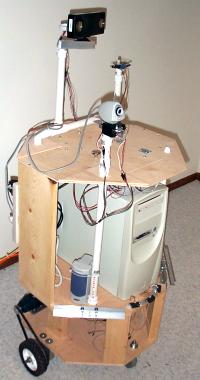 |
fig 9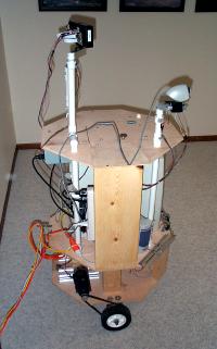 |
| Fig 8 - The Birds Eye View Here you can see the rotating sonar, Dinsmore compass, and the 2-Axis Webcam, 1 of 2 speakers, 2 bump switches, and 3 Sharp IR Sensors in front. The sonar rotates 180 degrees, and the IR Sensors are facing 330, 0 and 30 degrees relative to the front. |
Fig 9 - The Side View Here you can see more of the same. The PVC Pipe in design 3 needed re-enforced with some good old-fashion wood. |
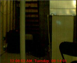
Some Computer Vision Tinkering...
As the robot was taking it's 1st look at the world I captured a few images. This one is of the basement. I have just started reading about some of the things going on a the The Computer Vision Home Page.
 |
 |
A simple VB program that gave me the bitmap above.
Just create a button, two picture boxes, then load your 1st picture box with the image you want to edit.
Private Sub Command1_Click()

For x = 0 To 352

For y = 0 To 288

newColor = Picture1.Point(x, y)

If newColor > 500000 Then

newbit = vbWhite

Else

newbit = vbBlack

End If

Picture2.PSet (x, y), newbit

Next

Next

End Sub
Summary
The past year of building Feynman has been very educational. I was distraught when during the summer I found another company building the robot that Feynman was going to be the prototype for but I continued my work none-the-less.
The goal a year ago was to just have the robot get me a beer. I was able to get the robot to do some simple things with the sonar it has taken most of my software efforts to reduce error of the sonar readings in the various environments. Leaving me to conclude the sonar it just not the best way for a robot to navigate.
Of course the goal of the navigation was very simple create a coordinate system from the world, remember that coordinate system and use it to find a point in the room that you wanted (The Fridge). After various configurations and software algorithms the errors thus far have been too high to compensate.
I avoided doing too much work with vision processing this far because I thought that sonar would be simpler. I am going to attempt one more effort with the sonar for that goto Feynman 2.

